Modelling cableway operations with PTV Vissim and PTV Viswalk
We usually associate cableways with transporting people in areas with rough terrain, for overcoming large height differences or as a tourist attraction. However, for a few years now they have increasingly been used as a means of urban transport. And exactly like classic means of transport such as buses, cars and trams, they and their passengers can be modelled with the microsimulation software PTV Vissim and the microscopic pedestrian simulation tool PTV Viswalk. We’ll show you how.
Different types of cableways
When modelling cableways, the type of train is highly significant, as is the boarding procedure. These differ between trains. The above video shows examples of two types of aerial cableway – firstly, a train with large cabins which stay still for boarding; next, small cabins which continue to move during boarding. In addition to that, two different types of boarding are shown.
The start of the animation shows a tram which is modelled using the standard public transport (PT) functionality in PTV Vissim. In addition to the network objects PT Lines and PT Stops, the special functions “Platform Edge” and “Waiting Area” for the network object (pedestrian) Area are available for this.
The boarding and alighting procedure for PTV Viswalk pedestrians at this stop is also controlled fully by the standard functionality. This is shown schematically in figure 1.
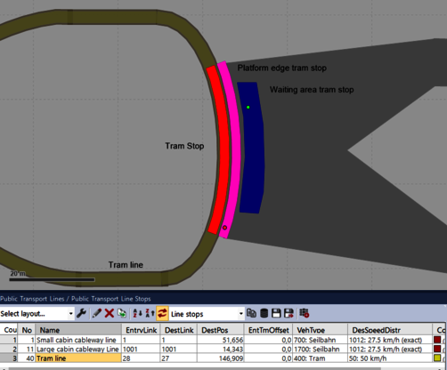
Figure 1
Cableway type 1: two large cabins which stop for boarding
Because the cableway with the large cabin shown in the video stops for the boarding procedure, it is essentially possible to model it using the PT standard functionality as well. However, there are a few aspects of the modelling to which it is worth drawing attention.
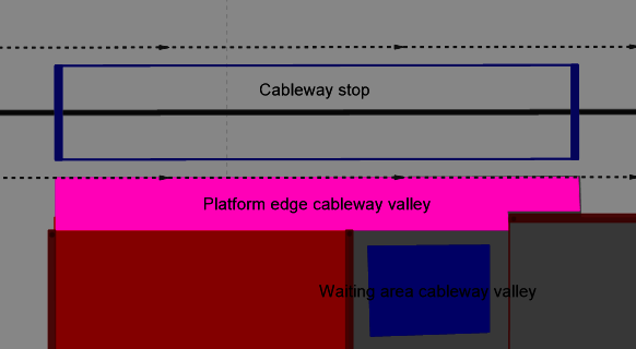
Figure 2
Cableway runs in a circle
Both of the cableway cabins run perpetually in a circle. This is not the norm for a PT Line. There is one trip along the route and at the end, the vehicle is removed from the simulation. However, you can achieve the desired behaviour with the help of a PT Partial Route. In doing so, the actual PT route can be very short and the stops are driven to using the PT partial route.
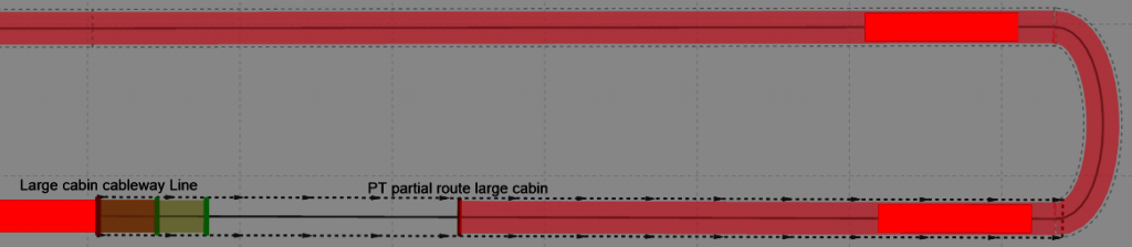
Figure 3
Modify railway height
For visualisation, it is interesting that the zero point of the height of the 3D model of the cabin is at a height of 10 metres in this case, namely at the support point on the cable. As such, the railway (Link) should also be placed at at least this height, because otherwise the cabins are shown as being underground. In order to correctly simulate the alighting and boarding processes for passengers, the width of the link must correspond to the width of the cabin. This is why the link should not be visible in the representation and a second, very narrow link should represent the cable. Figure 4 shows how it would look if the railway were not invisible.
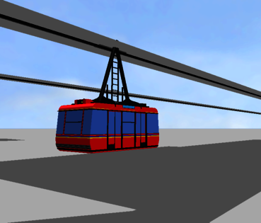
Figure 4
There are two cabins on the cable. Because they are connected by the cable, in reality they have exactly the same speed. They should, therefore, not become closer to each other over the course of the simulation. In this case, one circuit is almost 300 metres long. The cabins are therefore around 150 metres away from each other. If their speeds were to differ by only 0.05 km/h, they would run into each other during a three hour simulation. The speeds should therefore be as precisely identical to each other as possible. By editing the Distributions of Desired Speeds in the list, it is possible to generate a wholly clear distribution.
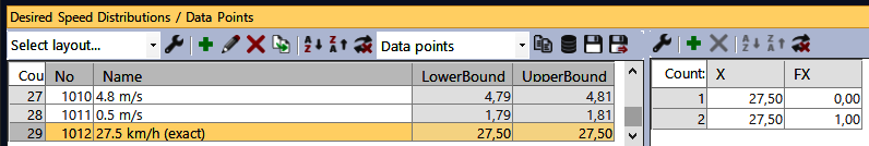
Figure 5
Figure 6
Modelling the set-up procedure
While in this example, boarding is processed by the standard functionality, it is more complicated to model the set-up process because in this case, the process has very specific characteristics. The capacity here, set in the Vehicle Type of a cabin, is 20 people. There are five waiting rooms in the model. A maximum of 20 people should wait in the first four. This gathers the “occupants” at an early stage. The arriving (future) passengers should keep to the sequence; they should not push to the front. This means that they should only enter a waiting room when it, all other waiting rooms and the access corridors do not contain more than 19 people in total. This is modelled using Partial Routes. Figure 7 shows the area structure and the first two Partial Route Decisions (10001 and 10002) with associated partial routes which either divert passengers into a waiting room or send them further along the corridor.
The partial route decisions are of the type Number. The Best Route is selected 100% of the time. The best route here is the one to which the smaller number of pedestrians is assigned. The partial route which continues down the corridor is always assigned the number 19.5, with the help of a small secondary model.
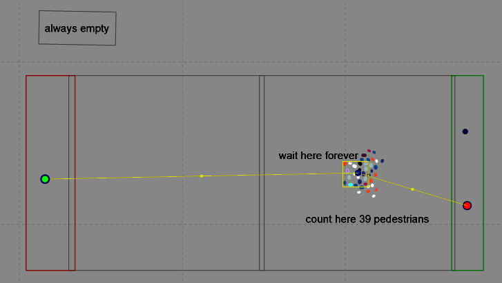
Figure 7
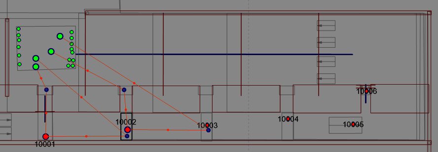
Figure 8
At the start of the simulation, exactly 39 pedestrians are deployed via the input from the left. A dwell time distribution with times greater than the duration of the simulation is assigned to the area called “wait here forever”. As such, there are 39 pedestrians in the area called “count here 39 pedestrians” throughout the entire simulation. Using the area called “always empty”, the number 19.5 can be made available with the “average” partial routes decision model.
The partial route which leads into the waiting room, however, is assigned the number of pedestrians in the area highlighted with a yellow border. This equates – as required – to all pedestrians who are in the relevant waiting room, all subsequent waiting rooms and in the corridor. As a result, a pedestrian is only diverted into the waiting room if there are fewer than 20 people in total in the aforementioned area.
But what happens if all the waiting rooms cannot cope with the level of demand? You can model this exceptional case using Service Point Selection Partial Route. This actually means that pedestrians can only be held for a certain amount of time before external events extend or shorten this time. You can circumvent this problem with a little trick: using a Signal Head prevents the pedestrian from reaching the “service point”, i.e. the head of the queue. Consequently, the waiting time does not start running. In the figure 10 you can see how the arrowhead which marks the front end of a queue is cut off by the signal head. This makes the waiting time itself very short. Overall, this has the effect that a maximum of 20 pedestrians, divided into 4 queues, gather in the rear waiting room, and any surplus individuals must wait in the corridor.
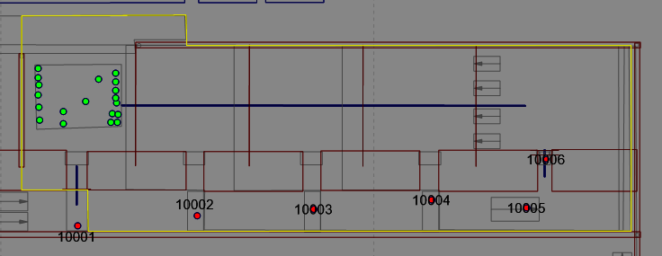
Figure 9
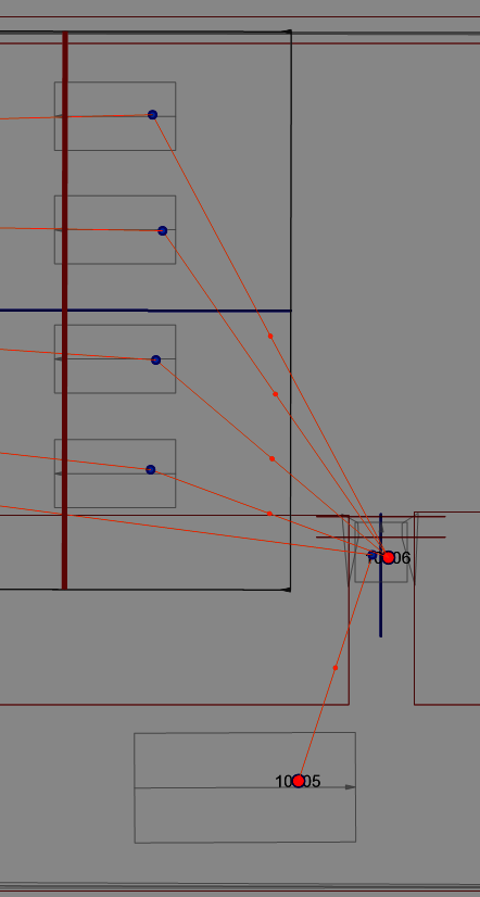
Figure 10
But when does the signal open? Signal heads 101 to 106 are controlled by a traffic-dependent logic (VAP) with input values which supply Detectors 101 to 103, as depicted in figure 11.
Initially, access to the first waiting room, from which the cabin can be accessed directly, should basically be denied if a cabin is there. I.e. the “enter waiting room” and “board cabin” processes should be at different points in time. This is regardless of the number of people waiting. For this, signal head 101 changes to red when detector 102 detects the cabin. It switches back to green if detector 103 detects the cabin and thus the cabin has left the boarding area. If detector 101 detects the cabin, a second VAP programme – cf. figure 12 – triggers signal head 102 switching initially from red to green, allowing passengers from the second into the – now empty – first waiting room. After some time (“Minimum Green Time”) the VAP programme switches signal head 102 back to red and, simultaneously, signal head 103 to green. It continues thus until all people waiting have been able to move into a waiting room.
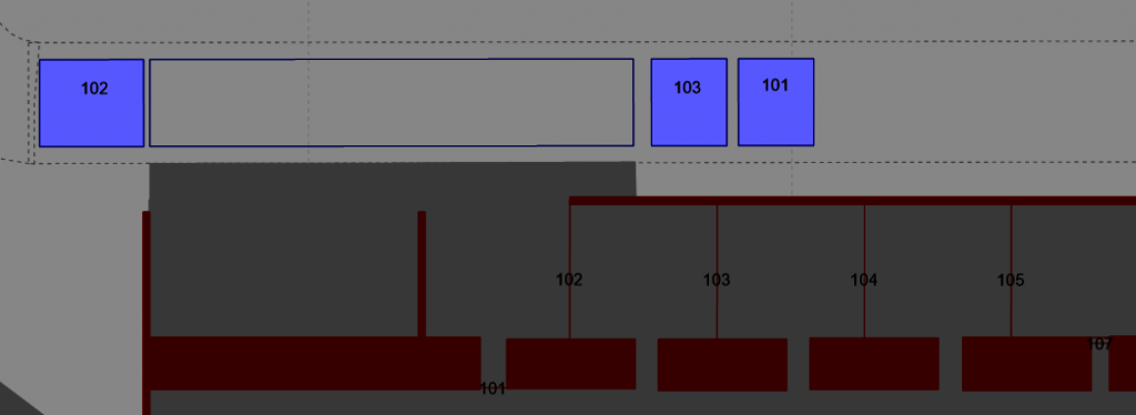
Figure 11
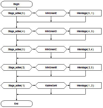
Figure 12
Cableway type 2: multiple small cabins which do not stop fully
The second cableway has smaller cabins with a capacity of four people. These cabins do slow down for the boarding process, but they do not stop entirely. Behaviour like this is not included in PTV Vissim’s standard PT functionality. However, modelling using scripts is possible.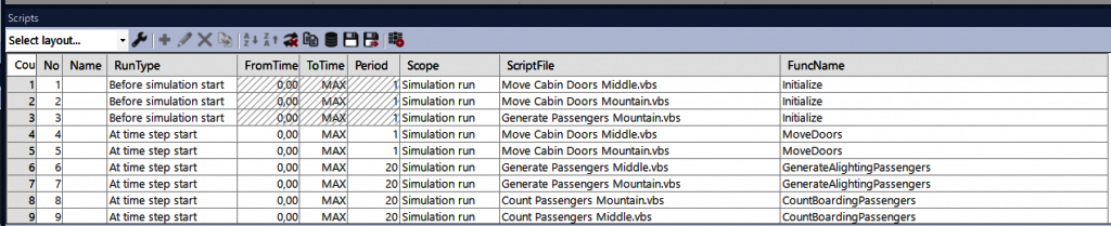
Figure 13
Scripts for the alighting and boarding process
This cableway’s alighting and boarding processes are regulated using three scripts, which are based on messages from multiple detectors.
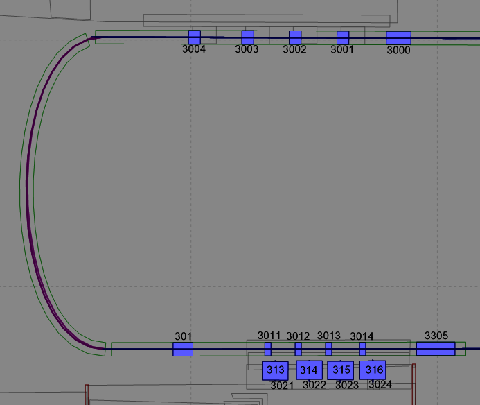
Figure 14: Detectors (bluish) in the disembarkation (above) and boarding area with channel numbers.
If detector 3000 reports a cabin, this means that, using the script “Move Cabin Doors Middle.vbs”, the cabin doors open in the 3D representation. If a corresponding number of people are in the cabin, riding over detectors 3001 to 3004 in the “Generate Passengers Middle.vbs” script triggers the creation of a pedestrian. Next, the cabin continues to travel, empty and with its doors open. The signal which is triggered by the presence of a cabin on detector 301 is not used in a script, but in VAP signal management “access control boarding areas.vap”. This sets a signal to red, which regulates access to the immediate waiting area. This prevents additional passengers waiting to board from entering the waiting area when the boarding process, for the cabin which is currently present, is not yet complete.
Next, the cabin drives over detectors 3011 to 3014. This means that signals 313 to 316 are briefly set to green, one after the other, enabling a passenger to board. Here too, a red signal prevents a pedestrian from reaching the head of a queue. Furthermore, in the “Count Passengers Middle.vbs” script, the “occupancy” attribute for the cabin increases by 1 due to an impulse on detector 3011 to 3014 triggered by the cabin when the associated detector 3021 to 3024 is occupied by a pedestrian. This ensures that the correct number of passengers alight from the cabin at a later point. It is important here that the cabin speed (0.5 m/s), the length of detectors 3011 to 3014 (0.5 m) and the running frequency of the counting script (once per second; here: every 20 simulation time steps) are in harmony with each other, to avoid counting duplicates. Lastly, the cabin runs over detector 3305, which triggers the shutting of the doors in the “Move Cabin Doors Middle.vbs” script.
As already mentioned: in the waiting area, a signaller is used at two points – when entering the boarding area and when boarding the cabin – to hold pedestrians back shortly before they reach the head of a queue. Figure 15 shows the partial routes that divide the boarding passengers into the four boarding positions, the signal heads and the areas which mark the queues.
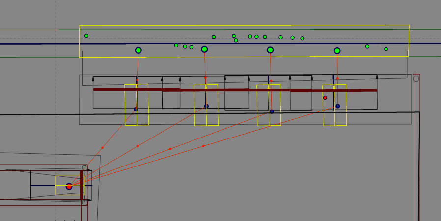
Figure 15