Alternative intersections modeling tips
Level: Advanced training topic
Understand your analysis objectives
PTV Vistro’s node and leg system provide unparalleled flexibility to create alternative intersections or innovative interchanges. The development of these advanced models starts with understanding your overall analysis objectives. You may be interested in only analyses; therefore, matching the basemap geometry exactly may take a back seat. For example, modeling a single-point urban interchange (SPUI) in schematic form is a straight forward process and may not even require a basemap.
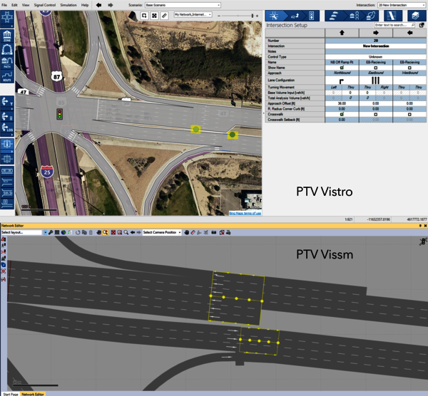
However, if you plan to supplement your alternative intersections analyses with advanced microsimulation in PTV Vissim, then geometry placement and location is very important. Your PTV Vistro network and position on the web base map will import to the exact location and scale in PTV Vissim. Using a basemap or conceptual design drawing to model your proposed alternative intersections will increase accuracy, as freehand coding of these configurations are difficult. To add a basemap, use the Map Layer tools and Insert a Background Image. To scale the image, use either the scaling tools for a precise size or drag the image corners. Additionally, the image can be moved into place on the web map.
What are the building blocks to your alternative intersections?
You may be eager to start modeling your alternative intersections, but a few seconds of planning will go a long way. The following should be identified during your planning process:
- Are the legs between intersections bi-directional or one-way?
- How many intersections and traffic signal controllers do I need?
- Can intersections be combined by using approach offsets and additional legs?
Determining the need bi-directional or one-way legs before you start is important. For example, the core of a diverging diamond intersection (DDI) or continuous flow intersection (CFI) will always use one-way legs to replicate the intricate flow patterns. But, innovative interchanges with large sweeping channelized roadways that intersect at different locations on the mainline may also benefit from one-way roadways. In these cases, impacts on the mainline are minimized, especially if the Vistro model is imported to PTV Vissim.
The decision to create one-way legs for this SPUI modeled in PTV Vistro was based on the merge/diverge locations of each channelized roadway. This provides a cleaner PTV Vissim export.
In addition, pre-planning the number of crossings helps determine the number of intersections that you need before you start modeling. This will also outline the final control types, signal groups, and overlaps needed to model your alternative intersection or innovative interchange designs.
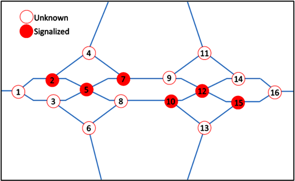
A sample of a pre-planning schematic of a diverging diamond interchange in before modeling in PTV Vistro.
Placing your first intersections
After planning the building blocks to your alternative intersections, you are ready to place your first junction. The following steps will increase your efficiency:
Select an intersection template
First, select an intersection template that is not the Unknown Control Type. Selecting a known control type temporarily accesses the advanced geometry features in the Intersection Setup workflow table. These include elements like speeds, medians, and entry/exit pockets. You can change the intersection back to Unknown later.
Layout your intersection
Next, place all intersections on PTV Vistro’s basemap according to your pre-planning schematic. At this time, exactness is not critical. Intersections can be adjusted into the final locations later. Also, there is no need to connect legs or create poly points for curvature just yet. Connecting legs will delete any curvature poly points and may create exit pockets accidentally. Additionally, for easier setup of lane configurations in later steps, keep the legs at the default 90-degree orientation. Lastly, renumber the intersections and provide intersection name descriptions according to your pre-planning schematic.
Delete or add extra legs
Next, delete or add extra intersection legs before assigning the lane configurations on each approach will simplify the process. To delete a leg, right-click on the leg grip to access the context menu. To add a leg, right-click on the intersections larger center node grip.
PTV Vistro can have up to 8-legs per intersection. If you have more than four legs on an approach, move additional legs to a 45-degree angle. This makes movement identification easier when setting up the lane configurations. In the Intersection Setup workflow table, it is highly recommended to add an approach name for each leg. This enables quick identification of the approach parameters in the workflow table, especially at locations with more than 4 legs.
Placing the approximate intersection locations in PTV Vistro and numbering based on the pre-planning schematic.
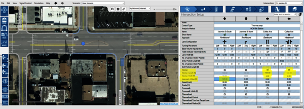
Enter Lane configurations
After the number of legs at each intersection is set, it is time to enter the Lane Configurations per approach in the Intersection Setup workflow table. The size of the workflow table can be adjusted by moving the vertical bar that separates the Network Editor web map from the table. Moreover, the workflow panel can be popped-out and expanded into a new window if you have multiple displays. Next, click on each movement's lane configuration and carefully select the correct turn template. Some intersections will likely be similar to others – perhaps a mirror image. Therefore, consider using PTV Vistro’s intersection copy-and-paste feature to recycle nodes. After pasting, use the leg grips to rearrange the node orientations.
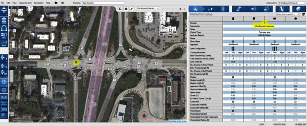
Entering the lane configurations to complete the alternative intersections and innovative interchange building blocks. PTV Vistro includes a useful intersection copy-and-paste feature to streamline modeling efforts.
Enter Lane configurations
After the number of legs at each intersection is set, it is time to enter the Lane Configurations per approach in the Intersection Setup workflow table. The size of the workflow table can be adjusted by moving the vertical bar that separates the Network Editor web map from the table. Moreover, the workflow panel can be popped-out and expanded into a new window if you have multiple displays. Next, click on each movement's lane configuration and carefully select the correct turn template. Some intersections will likely be similar to others – perhaps a mirror image. Therefore, consider using PTV Vistro’s intersection copy-and-paste feature to recycle nodes. After pasting, use the leg grips to rearrange the node orientations.
Entering the lane configurations to complete the alternative intersections and innovative interchange building blocks. PTV Vistro includes a useful intersection copy-and-paste feature to streamline modeling efforts.
Creating One-way Legs
Advanced alternative intersections or innovative interchanges may require creating one-way legs. These may be freeway on-ramps or off-ramp legs at your ramp terminal intersections.
Creating an Off-ramp (inbound/entering one-way leg)
Any leg that was added to the standard template will consist of an inbound one-way approach. Note: An outbound lane will be added automatically if the intersection contains a lane configuration turning to this leg.
But, if your inbound leg is not one-way already, you will need to modify it. To create this, all outbound lanes must be removed. To remove an outbound lane, right-click on the leg grip to open the context menu and select Remove Through Leg. However, this option is only available if the lane configurations of other legs do not include a turn to the outbound leg being removed. You will need to remove any conflicting lane configurations until Remove Through Leg is available.
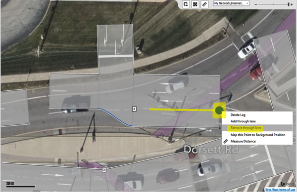
Removing intersection through lanes in PTV Vistro
Creating an On-ramp (outbound/exiting one-way leg)
Next, to create an outbound one-way leg, make sure that a lane configuration at the intersection assigns at least one turn to this outbound lane before deleting the lane configurations from the legs inbound approach side. This prevents the entire leg from deleting.
Verifying entry turn and exit pockets
After the lane configurations and legs are set up correctly, review and set the number of entry pockets (turn bays) and lengths to the correct values. This will create your entry pockets and set the storage lengths at each intersection.
Next, if you have lane drops on our outbound legs, enter the number of exiting pockets and the length to the lane drop locations. Exit pocket information is only entered on the side of the approach leg. Pockets can be entered on either the left or right side for outside or inside lane drops. Importantly, exit pockets can only be entered on legs with 2 or more lanes, and there must be at least 1 continuing lane on the leg.
Using entry and exit pockets can represent the geometry for acceleration and deceleration lanes at intersections or freeway ramp junctions.
Connecting legs and adjusting geometry
Finally, after the intersection legs are set up, they can be connected to the adjacent intersection legs by snapping the leg grips together.
Adding Poly Points
After the legs are joined, poly points can be added to help match the background geometry of your alternative intersections. To add a poly point, either right-click to open the context menu, then select insert poly point, or left-click and drag on the leg.
PTV Vistro’s network opacity can be updated using the Map Layers controls or by using the shortcut key combinations, CTRL+A or CTRL+W. This feature assists with aligning the legs and matching lane markings.
A complete DDI after connecting the building blocks legs and adding leg poly points.
Adjusting approach offsets
In the intersection setup, each approach leg has an Approach Offset value. A positive value in this field will slide the leg always to the right of the yellow centerline (regardless of the direction of traffic). Also, a negative value will shift the leg to the left. The offset value corresponds to the working units (ft or meters).
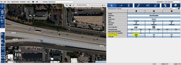
Adding approach offsets for freeway On-ramps in PTV Vistro
Approach offsets are instrumental in creating parallel facilities for on- and off-ramps. Also, this value is useful for intersections with one or more offset-T legs or at locations where through lanes do not align (see image below). At these locations, the measuring tool will help measure the offset distance from the basemap.
Adding Medians
Next, the addition of median islands will finalize the visual parameters for ANM export. Medians are created automatically with left-turn pockets (under right-hand traffic) based on the width of the left-turn lane entry pocket. Additional median widths can be added using the median checkbox and median width fields. The median length field is only used in the PTV Vissim ANM conversion to specify how long the median island is.
Adding medians and creating Offset-T intersections in PTV Vistro
Adding Signalization
Alternative intersections or innovative interchange designs have a variety of traffic signal control configurations and timings schemes. But, PTV Vistro’s flexible ring-barrier controller sequence and the phase diagram can replicate some of the most complicated signal setups. Reducing the number of signalized junctions is desirable. Intersections can share traffic signal controllers by selecting the same Controller ID number on the Traffic Control workflow table. When intersections share the same controller, the Sequence and Phase Diagram setup will be identical between intersections. Once shared, unused signal groups at each intersection will display in a lighter green color in the Phase Diagram.
Special signal groups can be made using the Signal Groups window on the Traffic Control workflow table. This menu is accessed by clicking the Plus icon next to the Default Signalization and Local Optimization tool icons. These additional signal groups coupled with Overlap control types on the Phasing & Timing section of the Traffic Control workflow table creates a variety of custom configurations.
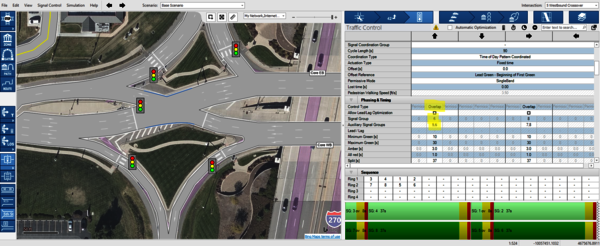
Utilizing a single controller for multiple intersections in PTV Vistro
Many innovative interchanges like DDIs and SPUIs include signalized on- or off-ramp turns to provide safe crossings for pedestrians and bicyclists. These typically would occur on a sweeping channelized roadway. Instead of modeling a signalized junction on the mainline, inserting a one-way signalized junction on the channelized roadway directly may provide a cleaner setup – especially when importing to PTV Vissim for simulation. This is accomplished by right-clicking on the channelized leg to open the context menu and selecting insert intersection ->signalized. The main roadway junction can then be later marked unsignalized.
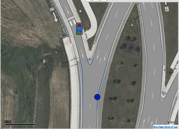
In PTV Vistro, adding a signalized intersection on a channelized roadway cleans up the import into PTV Vissim.
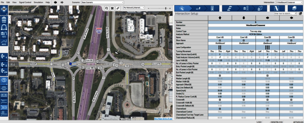
Making Unknown Intersections
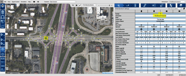
Finally, all intersections that are building nodes and that don’t have assigned traffic control devices should be changed to the Unknown control type on the Traffic Control workflow tab. To assist with this step, the Show Intersection Info graphic parameter for Control Type can be displayed to view each intersections traffic control. Intersections with Unknown control types do not have an icon, as shown in the image above.
Preview and Export to PTV Vissim
After inputting and balancing traffic volumes you can preview your PTV Vissim simulation or import into PTV Vissim using the ANM export.
PTV Vistro 2021’s improved ANM export functionality provides coordinate-based export of geometry; thus, providing an enhanced Vissim import. Additional ANM functionality in Vistro includes the visual representation, adjustments, and improved export of the turning radii, medians, and the stop bar and crosswalk positions. These improvements provide the exact intersection sizing an configuration of your intersection’s segment-analysis nodes. Utilizing PTV Vistro ultimately is a time-saving component to model and optimize your alternative intersections and innovative interchange designs.
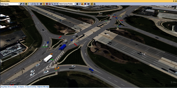
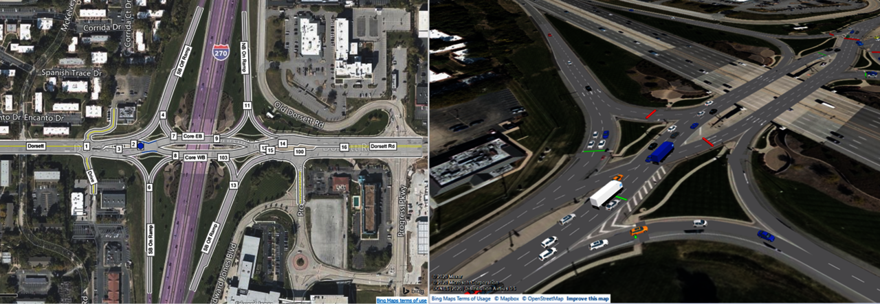
The DDI at I-270 along Dorsett Rd in Maryland Heights, MO created in PTV Vistro and imported to PTV Vissim.
Checkout our PTV Talks Vistro Webinar #6 on the topic of modeling Alternative Intersections and Innovative Interchanges in PTV Vistro and simulations in PTV Vissim.